728x90
테스트 환경
- Ubuntu 22.04
- TDA3XEVM
- PROCESSOR_SDK_VISION_03_08_00_00
TDA3xx Vision SDK 환경에서 UART2(SOC_UART2_BASE)를 통신 전용으로 추가하는 방법을 설명한다.
기존 디버그 UART(UART3, devId=2)는 그대로 유지하고, UART2를 CSL 레벨 폴링 방식으로 별도 구현한다.
┌──────────────┐     BSP GIO Driver      ┌─────────────┐
│  Debug Host  │◄────────────────────────►│ UART3       │  디버그 콘솔
│  (PC 터미널)  │     (인터럽트 방식)        │ devId=2     │  Vps_printf
└──────────────┘                          └─────────────┘

┌──────────────┐     CSL Polling Driver   ┌─────────────┐
│  UART        │◄────────────────────────►│ UART2       │  통신
│  외부 장치     │     (레지스터 직접 제어)     │ SOC_UART2   │
└──────────────┘                          └─────────────┘
UART를 활성화 하기 전에 해당 핀에 대한 클럭을 활성화 해야한다.
UART2 클럭은 SBL 부트로더가 활성화한다.
(`sbl_utils_tda3xx.c`의 `gModuleEnableTable`에 UART1/UART2 포함)

✔ UART2 클럭은 부트로더(SBL)에서 이미 활성화
➡ PRCM 별도 설정 불필요
✔ 하지만 핀 MUX 설정은 반드시 코드에서 직접 설정해야 함
→ UART2_RXD/PAD, UART2_TXD/PAD 각각 muxmode/pull-up 설정 필요
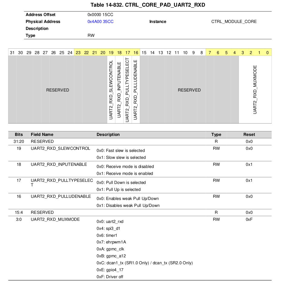
| 핀 | PAD 레지스터 오프셋 | 설정값 | 의미 |
|----|-------------------|--------|------|
| UART2_RXD | 0x4A003400 + 0x1CC | 0x00060000 | inputenable=1, pulluden=1, muxmode=0 |
| UART2_TXD | 0x4A003400 + 0x1D0 | 0x00000000 | muxmode=0 |

HW_WR_REG32(SOC_CORE_PAD_IO_REGISTERS_BASE + 0x1ccU, 0x00060000U);
HW_WR_REG32(SOC_CORE_PAD_IO_REGISTERS_BASE + 0x1d0U, 0x00000000U);

코드는 아래 ti에서 제공하는 기본 예제를 참고하였음
PROCESSOR_SDK_VISION_03_08_00_00/ti_components/drivers/pdk_01_10_04_05/packages/ti/drv/stw_lld/uartconsole/src/uartconsole.c
위 코드는 아래와 같은 순서로 초기화 (baud = 38400)
┌───────────────────────────────────────────┐
│                                           │
│  ① UARTModuleReset(base)                  │
│     → UART 모듈 소프트 리셋                   │
│                                            │
│  ② UARTFIFOConfig(base, fifoConfig)       │
│     → TX/RX FIFO 활성화 및 클리어             │
│     → TX trigger: 56바이트, RX trigger: 1   │
│                                            │
│  ③ UARTDivisorValCompute(48MHz, baud, 16x) │
│     → divisor = 48000000 / (16 × 38400)    │
│     → divisor = 78                         │
│                                            │
│  ④ UARTDivisorLatchWrite(base, 78)         │
│     → DLL = 78 & 0xFF = 0x4E               │
│     → DLH = 0x00                           │
│                                            │
│  ⑤ UARTRegConfigModeEnable(MODE_B)         │
│     → LCR = 0xBF (EFR 접근용)                │
│                                             │
│  ⑥ UARTLineCharacConfig(8N1)               │
│     → 8비트 데이터, 1 스톱비트, 패리티 없음       │
│                                             │
│  ⑦ UARTDivisorLatchDisable()               │
│     → DLAB 비트 클리어                        │
│                                             │
│  ⑧ UARTBreakCtl(DISABLE)                   │
│     → Break condition 비활성화                │
│                                             │
│  ⑨ UARTOperatingModeSelect(UART16x)         │
│     → MDR1[2:0] = 0 (UART 16x 모드)          │
│                                             │
└─────────────────────────────────────────────┘
| 레지스터 | 오프셋 | 역할 |
|---------|--------|------|
| RBR (Receive Buffer) | 0x00 | 수신 데이터 읽기 (DLAB=0) |
| THR (Transmit Holding) | 0x00 | 송신 데이터 쓰기 (DLAB=0) |
| DLL / DLH | 0x00 / 0x04 | Baud rate 분주기 (DLAB=1) |
| LCR (Line Control) | 0x0C | 8N1 설정 + DLAB 제어 |
| LSR (Line Status) | 0x14 | DR(bit0)=수신있음, THRE(bit5)=송신가능 |
| MDR1 (Mode Definition) | 0x20 | 동작모드 (0=UART16x) |
| SYSS (System Status) | 0x54 | RESETDONE(bit0) |
함수 내용은 아래 파일에서 확인 가능하다.
PROCESSOR_SDK_VISION_03_08_00_00/ti_components/drivers/pdk_01_10_04_05/packages/ti/csl/src/ip/uart/V1/priv/uart.c
파일안에 UARTCharPut을 통해 Write, UARTCharGet을 통해 Read 작업을 수행하면 된다.
void UARTCharPut(uint32_t baseAddr, uint8_t byteTx)
{
    uint32_t lcrRegValue = 0;

    /* Switching to Register Operational Mode of operation. */
    lcrRegValue = UARTRegConfigModeEnable(baseAddr, UART_REG_OPERATIONAL_MODE);

    /*
    ** Waits indefinitely until the THR and Transmitter Shift Registers are
    ** empty.
    */
    while (((uint32_t) UART_LSR_TX_SR_E_MASK |
            (uint32_t) UART_LSR_TX_FIFO_E_MASK) !=
           (HW_RD_REG32(baseAddr + UART_LSR) &
            ((uint32_t) UART_LSR_TX_SR_E_MASK |
             (uint32_t) UART_LSR_TX_FIFO_E_MASK)))
    {
        /* Do nothing - Busy wait */
    }

    HW_WR_REG32(baseAddr + UART_THR, (uint32_t) byteTx);

    /* Restoring the value of LCR. */
    HW_WR_REG32(baseAddr + UART_LCR, lcrRegValue);
}
/**
 * \brief    This API waits indefinitely for the arrival of a byte in
 *           the receiver FIFO. Once a byte has arrived, it returns that
 *           byte.
 *
 * \param    baseAddr     Memory address of the UART instance being used.
 *
 * \return   This returns the read byte.
 */

int8_t UARTCharGet(uint32_t baseAddr)
{
    uint32_t lcrRegValue = 0;
    int8_t   retVal      = 0;
    uint32_t tempRetVal  = 0;

    /* Switching to Register Operational Mode of operation. */
    lcrRegValue = UARTRegConfigModeEnable(baseAddr, UART_REG_OPERATIONAL_MODE);

    /* Waits indefinitely until a byte arrives in the RX FIFO(or RHR). */
    while ((uint32_t) UART_LSR_RX_FIFO_E_RX_FIFO_E_VALUE_0 ==
           (HW_RD_REG32(baseAddr + UART_LSR) &
            UART_LSR_RX_FIFO_E_MASK))
    {
        /* Do nothing - Busy wait */
    }

    tempRetVal = HW_RD_REG32(baseAddr + UART_RHR);
    retVal     = ((int8_t) tempRetVal);

    /* Restoring the value of LCR. */
    HW_WR_REG32(baseAddr + UART_LCR, lcrRegValue);

    return retVal;
}
728x90
'TI > TDA3' 카테고리의 다른 글
| Vision SDK에서 NDK 네트워크 통신 구성하기 (0) | 2026.03.20 |
|---|---|
| Draw2D를 이용해 한글 표시 (0) | 2025.12.31 |
| I2C SLAVE MODE (0) | 2025.06.03 |
| Vision SDK Usecase 사용 방법 (0) | 2025.04.16 |
| CSL Example 프로그램 사용 방법 (0) | 2025.04.12 |