
이전에 수동제어1에서 했던거를 이어서
  GPIO_InitTypeDef GPIO_InitStruct = {0};
  GPIO_InitStruct.Pin = GPIO_LED_Pin; //PC13 1 << 13
  GPIO_InitStruct.Mode = GPIO_MODE_OUTPUT_PP;
  GPIO_InitStruct.Pull = GPIO_PULLDOWN;
  GPIO_InitStruct.Speed = GPIO_SPEED_FREQ_HIGH;
  HAL_GPIO_Init(GPIO_LED_GPIO_Port, &GPIO_InitStruct);
이제 HAL_GPIO_WritePin() 해석이 끝났으니 GPIO_InitStruct에 대해서 해석해보자면 우선 GPIO_InitTypeDef GPIO_InitStruct = {0}; 구조체를 확인해보면 다음과 같이 구성되어 있다.
typedef struct
{
  uint32_t Pin;       /*!< Specifies the GPIO pins to be configured.
                           This parameter can be any value of @ref GPIO_pins_define */

  uint32_t Mode;      /*!< Specifies the operating mode for the selected pins.
                           This parameter can be a value of @ref GPIO_mode_define */

  uint32_t Pull;      /*!< Specifies the Pull-up or Pull-Down activation for the selected pins.
                           This parameter can be a value of @ref GPIO_pull_define */

  uint32_t Speed;     /*!< Specifies the speed for the selected pins.
                           This parameter can be a value of @ref GPIO_speed_define */
} GPIO_InitTypeDef;
하나씩 순서대로 GPIO_InitStruct.Pin = GPIO_LED_Pin; 먼저 확인해보자면 아까 위에서 확인했듯이 8192 값이 들어가게 된다.
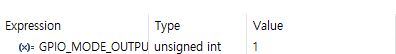
GPIO_InitStruct.Mode = GPIO_MODE_OUTPUT_PP; 는 값을 확인해보면 다음과 같이 나온다.
GPIO_InitStruct.Pull = GPIO_PULLDOWN; 는 값을 확인해보면 다음과 같이 나온다.

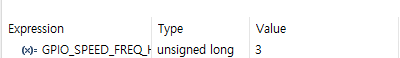
GPIO_InitStruct.Speed = GPIO_SPEED_FREQ_HIGH; 는 값을 확인해보면 다음과 같이 나온다.
값을 다 확인했으니 HAL_GPIO_Init(GPIO_LED_GPIO_Port, &GPIO_InitStruct); 에 대해서 알아보자 먼저 2개의 매개변수를 보내게 되는데 여기서 GPIO_LED_GPIO_Port는 Ctrl + 마우스 클릭으로 들어가면 GPIOC가 나오고 &GPIO_InitStruct는 방금 위에서 구한 값들이다. 이제 코드안으로 들어가게 되면 다음과 같이 나온다.
void HAL_GPIO_Init(GPIO_TypeDef  *GPIOx, GPIO_InitTypeDef *GPIO_Init)
{
  uint32_t position = 0x00u;
  uint32_t ioposition;
  uint32_t iocurrent;
  uint32_t temp;
  uint32_t config = 0x00u;
  __IO uint32_t *configregister; /* Store the address of CRL or CRH register based on pin number */
  uint32_t registeroffset;       /* offset used during computation of CNF and MODE bits placement inside CRL or CRH register */

  /* Check the parameters */
  assert_param(IS_GPIO_ALL_INSTANCE(GPIOx));
  assert_param(IS_GPIO_PIN(GPIO_Init->Pin));
  assert_param(IS_GPIO_MODE(GPIO_Init->Mode));

  /* Configure the port pins */
  while (((GPIO_Init->Pin) >> position) != 0x00u)
  {
    /* Get the IO position */
    ioposition = (0x01uL << position);

    /* Get the current IO position */
    iocurrent = (uint32_t)(GPIO_Init->Pin) & ioposition;

    if (iocurrent == ioposition)
    {
      /* Check the Alternate function parameters */
      assert_param(IS_GPIO_AF_INSTANCE(GPIOx));

      /* Based on the required mode, filling config variable with MODEy[1:0] and CNFy[3:2] corresponding bits */
      switch (GPIO_Init->Mode)
      {
        /* If we are configuring the pin in OUTPUT push-pull mode */
        case GPIO_MODE_OUTPUT_PP:
          /* Check the GPIO speed parameter */
          assert_param(IS_GPIO_SPEED(GPIO_Init->Speed));
          config = GPIO_Init->Speed + GPIO_CR_CNF_GP_OUTPUT_PP;
          break;

        /* If we are configuring the pin in OUTPUT open-drain mode */
        case GPIO_MODE_OUTPUT_OD:
          /* Check the GPIO speed parameter */
          assert_param(IS_GPIO_SPEED(GPIO_Init->Speed));
          config = GPIO_Init->Speed + GPIO_CR_CNF_GP_OUTPUT_OD;
          break;

        /* If we are configuring the pin in ALTERNATE FUNCTION push-pull mode */
        case GPIO_MODE_AF_PP:
          /* Check the GPIO speed parameter */
          assert_param(IS_GPIO_SPEED(GPIO_Init->Speed));
          config = GPIO_Init->Speed + GPIO_CR_CNF_AF_OUTPUT_PP;
          break;

        /* If we are configuring the pin in ALTERNATE FUNCTION open-drain mode */
        case GPIO_MODE_AF_OD:
          /* Check the GPIO speed parameter */
          assert_param(IS_GPIO_SPEED(GPIO_Init->Speed));
          config = GPIO_Init->Speed + GPIO_CR_CNF_AF_OUTPUT_OD;
          break;

        /* If we are configuring the pin in INPUT (also applicable to EVENT and IT mode) */
        case GPIO_MODE_INPUT:
        case GPIO_MODE_IT_RISING:
        case GPIO_MODE_IT_FALLING:
        case GPIO_MODE_IT_RISING_FALLING:
        case GPIO_MODE_EVT_RISING:
        case GPIO_MODE_EVT_FALLING:
        case GPIO_MODE_EVT_RISING_FALLING:
          /* Check the GPIO pull parameter */
          assert_param(IS_GPIO_PULL(GPIO_Init->Pull));
          if (GPIO_Init->Pull == GPIO_NOPULL)
          {
            config = GPIO_CR_MODE_INPUT + GPIO_CR_CNF_INPUT_FLOATING;
          }
          else if (GPIO_Init->Pull == GPIO_PULLUP)
          {
            config = GPIO_CR_MODE_INPUT + GPIO_CR_CNF_INPUT_PU_PD;

            /* Set the corresponding ODR bit */
            GPIOx->BSRR = ioposition;
          }
          else /* GPIO_PULLDOWN */
          {
            config = GPIO_CR_MODE_INPUT + GPIO_CR_CNF_INPUT_PU_PD;

            /* Reset the corresponding ODR bit */
            GPIOx->BRR = ioposition;
          }
          break;

        /* If we are configuring the pin in INPUT analog mode */
        case GPIO_MODE_ANALOG:
          config = GPIO_CR_MODE_INPUT + GPIO_CR_CNF_ANALOG;
          break;

        /* Parameters are checked with assert_param */
        default:
          break;
      }

      /* Check if the current bit belongs to first half or last half of the pin count number
       in order to address CRH or CRL register*/
      configregister = (iocurrent < GPIO_PIN_8) ? &GPIOx->CRL     : &GPIOx->CRH;
      registeroffset = (iocurrent < GPIO_PIN_8) ? (position << 2u) : ((position - 8u) << 2u);

      /* Apply the new configuration of the pin to the register */
      MODIFY_REG((*configregister), ((GPIO_CRL_MODE0 | GPIO_CRL_CNF0) << registeroffset), (config << registeroffset));

      /*--------------------- EXTI Mode Configuration ------------------------*/
      /* Configure the External Interrupt or event for the current IO */
      if ((GPIO_Init->Mode & EXTI_MODE) == EXTI_MODE)
      {
        /* Enable AFIO Clock */
        __HAL_RCC_AFIO_CLK_ENABLE();
        temp = AFIO->EXTICR[position >> 2u];
        CLEAR_BIT(temp, (0x0Fu) << (4u * (position & 0x03u)));
        SET_BIT(temp, (GPIO_GET_INDEX(GPIOx)) << (4u * (position & 0x03u)));
        AFIO->EXTICR[position >> 2u] = temp;


        /* Configure the interrupt mask */
        if ((GPIO_Init->Mode & GPIO_MODE_IT) == GPIO_MODE_IT)
        {
          SET_BIT(EXTI->IMR, iocurrent);
        }
        else
        {
          CLEAR_BIT(EXTI->IMR, iocurrent);
        }

        /* Configure the event mask */
        if ((GPIO_Init->Mode & GPIO_MODE_EVT) == GPIO_MODE_EVT)
        {
          SET_BIT(EXTI->EMR, iocurrent);
        }
        else
        {
          CLEAR_BIT(EXTI->EMR, iocurrent);
        }

        /* Enable or disable the rising trigger */
        if ((GPIO_Init->Mode & RISING_EDGE) == RISING_EDGE)
        {
          SET_BIT(EXTI->RTSR, iocurrent);
        }
        else
        {
          CLEAR_BIT(EXTI->RTSR, iocurrent);
        }

        /* Enable or disable the falling trigger */
        if ((GPIO_Init->Mode & FALLING_EDGE) == FALLING_EDGE)
        {
          SET_BIT(EXTI->FTSR, iocurrent);
        }
        else
        {
          CLEAR_BIT(EXTI->FTSR, iocurrent);
        }
      }
    }

	position++;
  }
}
코드가 길지만 하나씩 확인해보면 assert_param은 아까와 같이 별 중요한 함수는 아니다. 간단히 말하자면 안에 들어간 매개변수 값이 유효한지 아니면 경고를 나타내는 등 메시지를 보여주는 함수이다. 그 다음 볼 것은 while문인데 사실 상 while문 하나에서 다 끝나는 함수이다.
while(((GPIO_Init->Pin)>>position)!=0x00u){
position++;
}//
Binary:
1000000000000
0100000000000
0010000000000
...
0000000000001
0000000000000 <- 이때 멈춤.
GPIO_Init->Pin 값은 위에서 확인한 8192(1<<13)인데 이를 position 만큼 >> 비트연산하고 0x00u(0)와 같지 않으면 반복하는 반복문이다. 즉 position값이 증가하면서 값이 14가 되면 Pin 값이 0이 되기떄문에 반복문을 빠져나가게 된다.
이제 반복문 안으로 들어가 다음 코드를 확인해보면
ioposition = (0x01uL << position);
1
10
100
1000
ioposition은 1을 position 만큼 << 비트연산을 하여 대입한다.
iocurrent = (uint32_t)(GPIO_Init->Pin) & ioposition;
1 ioposition
10 0000 0000 0000 & GPIO_Init->Pin
0 iocurrent
if (iocurrent == ioposition)
{
}
if문에 들어가기 위해서 반복문이 끝나면서 position 값이 계속 증가하여 ioposition 값이 and 연산을 통해 다음과 같이 된다면 if문 안에 들어갈 수 있게 된다.(Pin이 몇번째 Pin인지 알기 위해서 진행하는 if문 같다.)
10 0000 0000 0000 ioposition
10 0000 0000 0000 & GPIO_Init->Pin
10 0000 0000 0000 iocurrent
이어서 if문 안에 들어가게 되면 다음과 같은 swith문이 나오게 되는데 GPIO_Init->Mode 값은 위에서 구했던 1이다. 이로 인해 switch문 안으로 들어가게 된다. 들어가서 확인해보면 여러 case 문이 나오게 된다. 위에서 GPIO_InitStruct.Mode = GPIO_MODE_OUTPUT_PP; 으로 설정했기 때문에 첫번째 case문으로 들어가게 된다.
switch (GPIO_Init->Mode)
{
case GPIO_MODE_OUTPUT_PP:
assert_param(IS_GPIO_SPEED(GPIO_Init->Speed));
config = GPIO_Init->Speed + GPIO_CR_CNF_GP_OUTPUT_PP;
break;
...
}
config 값을 구해보면 위에서 구했던 GPIO_Init->Speed 값은 3 뒤에 GPIO_CR_CNF_GP_OUTPUT_PP; 값은 확인해보면 다음과 같이 나온다.
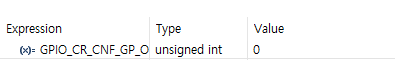
고로 config 값은 3+0인 3이 나오게 된다. config 값을 구했으면 바로 break 문을 통해 switch문을 빠져나가게 된다.
빠져 나간 뒤 다음 코드를 해석해보자면
configregister = (iocurrent < GPIO_PIN_8) ? &GPIOx->CRL     : &GPIOx->CRH;
registeroffset = (iocurrent < GPIO_PIN_8) ? (position << 2u) : ((position - 8u) << 2u);

MODIFY_REG((*configregister), ((GPIO_CRL_MODE0 | GPIO_CRL_CNF0) << registeroffset), (config << registeroffset));
우선 configregister와 registeroffset 의 (iocurrent < GPIO_PIN_8)를 보자면 iocurrent는 위에서 계산했듯이 1<<13 한 값이다. GPIO_PIN_8 값은 확인해보면 0x100(1<<8) 값이 나오게 되는데 이거를 해석하자면 삼항연산에 의해 값이 참일경우 &GPIOX->CRL가 실행되고 거짓일경우 &GPIOx->CRH가 실행된다. 즉 0~7핀까지는 &GPIOx->CRL, (position << 2u) 그 이상은 &GPIOx->CRH, ((position - 8u) << 2u)
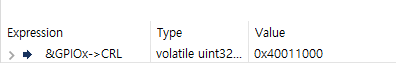
&GPIOX->CRL의 값을 확인해보면 다음과 같이 나온다.
&GPIOx->CRH의 값을 확인해보면 다음과 같이 나온다.

고로 configregister의 값은 0x40011004가 들어가게 된다.
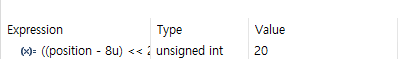
이어서 registeroffset는 삼항연산 결과에 의해 ((position - 8u) << 2u)가 실행되는데 ((13 - 8) << 2u)을 하면 registeroffset는 20이라는 값이 나오게 된다.
마지막으로 MODIFY_REG()에 대해서 보자면 우선 Ctrl + 마우스 클릭으로 코드를 클릭하면 다음과 같이 나온다.
#define MODIFY_REG(REG, CLEARMASK, SETMASK)  WRITE_REG((REG), (((READ_REG(REG)) & (~(CLEARMASK))) | (SETMASK)))

#define WRITE_REG(REG, VAL)   ((REG) = (VAL))

#define READ_REG(REG)         ((REG))
REG에는 위에서 구한 *configregister의 값인 *(0x40011004)가 들어가게 된다.
CLEARMASK에는 GPIO_CRL_MODE0 | GPIO_CRL_CNF0 << registeroffset 값이 들어가는데 여기서 GPIO_CRL_MODE0 | GPIO_CRL_CNF0 값을 확인해보면 다음과 같이 나온다.
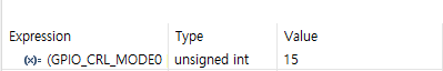
고로 15 << 20의 값인 15,728,640가 들어가게 된다
SETMASK에는 위에서 구한 config << registeroffset 즉 3 << 20의 값인 3,145,728가 들어가게 된다.
그 다음 WRITE_REG(REG,VAL)에 대해 보자면 REG는 위에서 구한 *(0x40011004)가 들어가게 되고 VAL은 ((READ_REG(REG)) & (~(CLEARMASK))) | (SETMASK)) 값이 들어가는데 위에서 구한 값을 대입해보자면
*(0x40011004) = (*(0x40011004) & ~( 15 << 20)) | (3 << 20); 이 나오게 된다. 즉 맨 처음 적은 6줄의 코드는 밑에 코드와 같다.
 GPIO_InitTypeDef GPIO_InitStruct = {0};
GPIO_InitStruct.Pin = GPIO_LED_Pin;
GPIO_InitStruct.Mode = GPIO_MODE_OUTPUT_PP;
GPIO_InitStruct.Pull = GPIO_PULLDOWN;
GPIO_InitStruct.Speed = GPIO_SPEED_FREQ_HIGH;
HAL_GPIO_Init(GPIO_LED_GPIO_Port, &GPIO_InitStruct);

=

volatile unsinged int * reg2 = 0x40011004
*reg2 = (*reg2 & ~( 15 << 20)) | (3 << 20);
이를 토대로 코드를 수정하자면
volatile unsigned int * reg = 0x40021018;
  *reg |= 16;

  volatile unsigned int * reg2 = 0x40011004;
   *reg2 = (*reg2 & ~(15UL << 20U )) | (3U << 20U);

  /* USER CODE END 2 */

  /* Infinite loop */
  /* USER CODE BEGIN WHILE */
  volatile unsigned int * reg3 = 0x40011010;
  while (1)
  {
	  *reg3 = 0x2000;
	  HAL_Delay(100);
	  *reg3 = (0x2000 << 16);
	  HAL_Delay(100);
    /* USER CODE END WHILE */

    /* USER CODE BEGIN 3 */
  }
  /* USER CODE END 3 */
}
위의 코드를 넣고 디버깅을 하게 되면 PC13에 연결된 내장 LED가 깜빡이는 것을 확인할 수 있다.
전체 코드https://github.com/rorosi/STM32F103C8T6/blob/main/LED/GPIO_%EC%88%98%EB%8F%99%EC%A0%9C%EC%96%B42.c
GitHub - rorosi/STM32F103C8T6
Contribute to rorosi/STM32F103C8T6 development by creating an account on GitHub.
github.com
'STM32 > STM32F103C8T6' 카테고리의 다른 글
| GPIO_LED_수동제어1 (0) | 2021.12.31 |
|---|